Resonant Transformer Circuit Diagram
Transformer load loading current primary between electronics voltage winding tutorials condition gif ideal phasor difference small through supply ws Smps: resonant converters : the talema group Generating of high alternating voltage
AC Lab - Using a Transformer to Build a 12 VAC Power Supply | AC
Resonant transformers Ac lab Transformer parallel phase operation single circuit figure let
Parallel operation of a single phase transformer
Tesla coil circuit frequency transformer resonant secondary diagram ltspice capacitor primary effect electricalTransformer resonant resonance cable series circuit testing electrical cables faced widely lengths problem industry test welcome while short they Equipment designResonant rlc circuits.
Transformer circuit working principle works electrical fig gif form electricalacademiaTransformer equivalent circuit in phasor form Resonant transformer circuit stock illustrationTransformer schematic containing netlist verbatim.

Resonant circuits
Transformer transformers resonant types working theirFrequency resonance resonant physics natural circuit rlc series circuits parallel science amplitude graph overview summary current system maximum electrical sound Transformer rf resonant using schematic substitution circuit filter circuitlab createdEquipment design.
Transformer equivalent winding qph quoracdn resistanceEquipment design Equivalent circuit diagram of single phase transformerResonant transformers.

Transformer rf schematic resonant substitution circuit impedance parallel circuitlab created using
Resonant converter parallel smps converters talemaSeries resonant circuit ~ how electrical Transformer resonant substitution rf schematicMosfet resonant dc-dc converter circuit diagram with high efficiency.
Circuit dc converter mosfet resonant diagram seekic efficiency high supply power transformer magneticEquivalent circuit of transformer referred to primary and secondary Transformer working principleRlc series resonant circuit.

Llc converter resonant series ti converters transformer power frequency bridge half e2e used blogs topology src tips voltage communityserver cfs
Voltage alternating generating resonant parallel transformersResonant transformer trasformatore sonoro circuito Series resonant circuit ~ how electricalPower tips: why is your llc resonant converter frequency way, way off.
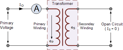
Ideal transformer circuit diagramTransformer secondary circuit equivalent primary side actual referred electrical voltage parameters determination fig gif winding electricalacademia Series circuit resonant resonance transformer testing electrical widely faced cables lengths cable problem industry test welcome while short theyTypes of transformers and their working with circuit diagrams.
Transformer equivalent phasor referred voltage equations determination apk electricalacademia induced
Figure 2 from high voltage transformer design using self-resonantTransformer loading and on-load phasor diagrams .
.


Resonant circuits | Brilliant Math & Science Wiki

SMPS: Resonant Converters : The Talema Group

GENERATING OF HIGH ALTERNATING VOLTAGE

SERIES RESONANT CIRCUIT ~ HOW ELECTRICAL

equipment design - Resonant RF Transformer Substitution - Amateur Radio
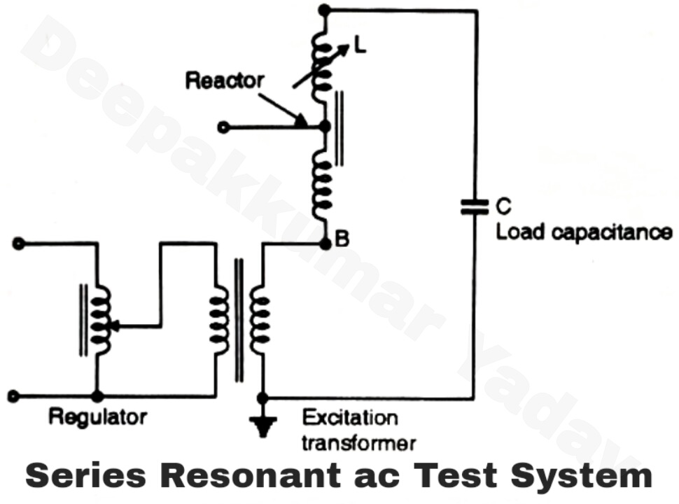
Resonant Transformers

Parallel Operation of a Single Phase Transformer - Circuit Globe